
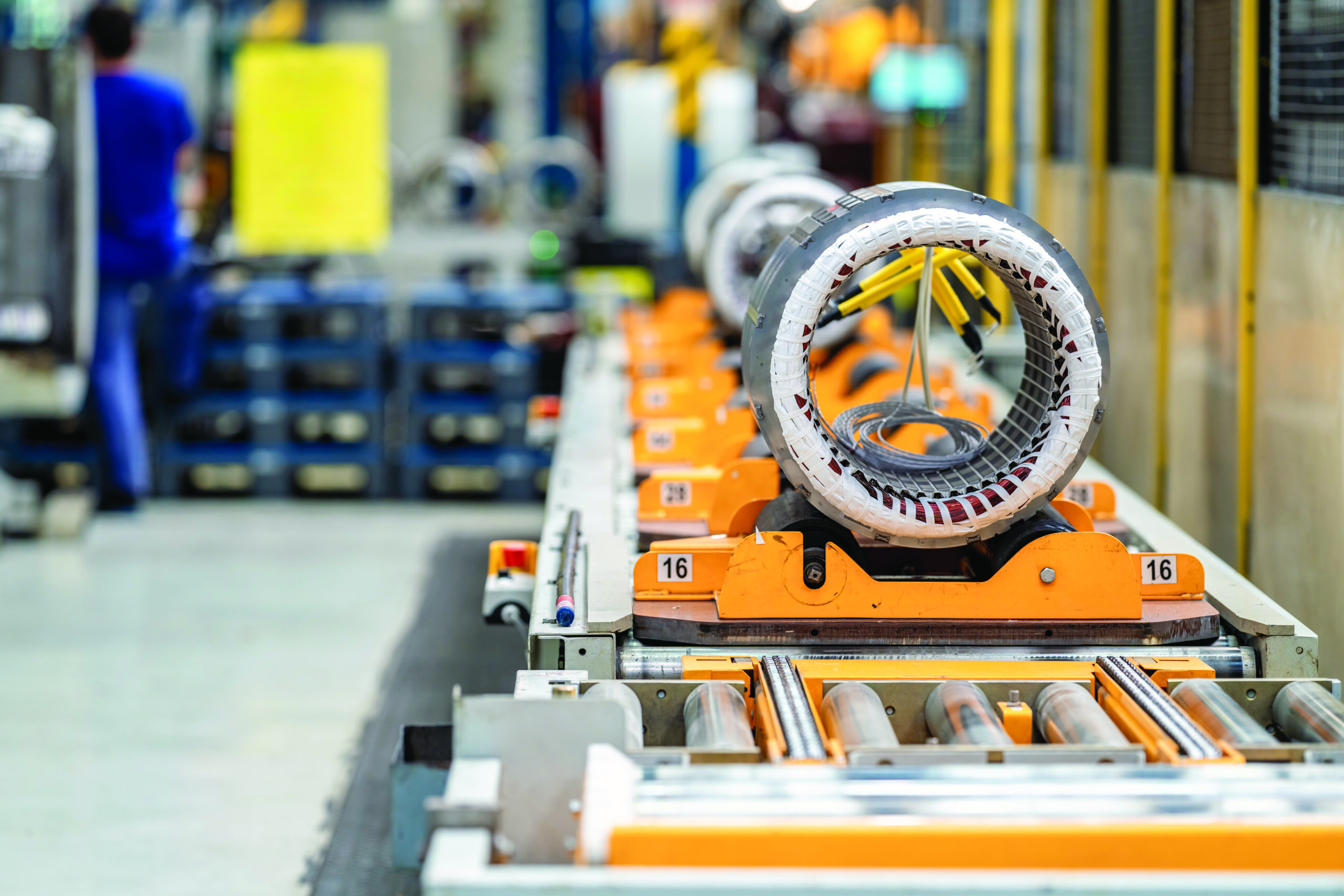
The EV story is often told through batteries and motors. But behind every efficient motor is a precision die that shapes the steel laminations inside it. From stamping 0.20 mm traction laminations to controlling burrs and meeting hairpin winding tolerances, the die plays a crucial role in ensuring motor efficiency. As EV manufacturing grows in India, tool rooms that can build high-precision lamination dies could play a key role in developing the electric drivetrain ecosystem.
Pull apart an EV traction motor, and the part that determines how well it runs is not the copper you can see or the magnets you can feel. It is a stack of steel sheets, each one thinner than a bank card, pressed together into a cylinder with slots cut around its inner face. That stack is the stator core. Every sheet in it was punched out using a stamping die. How efficiently the motor converts battery energy into road speed depends, to a surprising degree, on how well that die was made. This part of the EV story sits squarely inside a tool room’s wheelhouse and is rarely talked about. What actually happens when a lamination is stamped? Why is it so difficult to do well? And why do India’s precision toolmakers have every reason to pay attention? Let’s find out…
Why is the Steel so Thin?
Start with a basic question. If you need a chunk of magnetic steel to carry the motor’s magnetic field, why cut it into hundreds of paper-thin sheets instead of using one solid block?
The answer is eddy currents. When a magnetic field changes rapidly inside a solid piece of metal, it induces little swirling currents within the steel itself. Those currents do no useful work. They only heat the steel and waste energy. In a traction motor spinning at 15,000 rpm or more, the field changes direction hundreds of times a second. A solid core would lose too much energy as heat.
Slicing the core into thin, electrically insulated layers breaks up those swirling currents and starves them. Each sheet carries a thin coating so it does not conduct sideways into its neighbour. The thinner each sheet, the smaller the losses. That is why traction motors have pushed from the old 0.50 mm and
0.35 mm sheet used in industrial motors down to 0.25 mm, 0.20 mm, and in high-speed designs, even thinner. thyssenkrupp’s traction grade material, for example, sits in the 0.20 to 0.35 mm band and is alloyed to hold up at 20,000 rpm, a speed conventional grades cannot survive.
That thinness is where the tooling difficulty begins. A die that punches 0.50 mm mild steel is one thing. A die punching 0.20 mm silicon steel, cleanly, millions of times, belongs in a different league.
The Die, the Tonnage, and the Tolerances
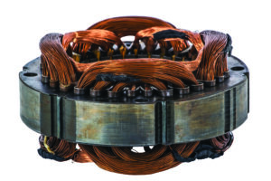
Traction motor laminations in volume are made on progressive dies. A coil of electrical steel feeds into the press, and the strip moves through the tool one station at a time. Each station does one simple job: a pierce here, a slot there, a notch, a bend, until the finished lamination drops out at the last station. Thinner gauges and more complex slot geometries need more stations. This means longer dies and longer press beds.
The numbers involved are unforgiving. Modern progressive dies hold slot-width tolerances around plus or minus 0.02 to 0.03 mm, and outer-diameter tolerances near plus or minus 0.05 mm. Presses run anywhere from 100 to 600 strokes a minute for these parts, and the fastest lines push past 1,000. A single complex stator die can cost between USD 80,000 and USD 300,000 to build, which means the tool has to run enormous volumes before it pays for itself. Good die makers quote lifespans in the hundreds of millions of strokes, and they get there by cutting the working parts from tungsten carbide rather than tool steel.
Why carbide? Because electrical steel is abrasive. The same silicon content that gives the steel its magnetic properties also makes it hard on cutting edges. A steel punch that would blunt in a shift can be replaced by carbide that holds its edge across tens of millions of hits. For a toolmaker, this is not a small detail. It changes how you design the die, how you mount and locate the inserts, and how you plan for regrinding.
The Burr is the Enemy
The single quality parameter that separates a good lamination from a bad one is burr height.
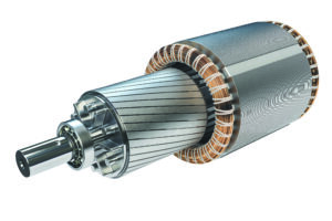
When a punch shears through steel, it leaves a small ragged lip on the cut edge. That lip is the burr. On most stamped parts, a burr is a cosmetic nuisance. On a motor lamination, it is a functional defect, because the burr on one sheet can bridge across to the sheet above it and break through the insulating coating. Once two neighbouring sheets touch electrically, you have handed the eddy currents a path around the very insulation that was meant to stop them. Poorly controlled burrs can raise a core’s eddy-current losses by 15–20%. The motor gets hotter and less efficient, and no clever winding design will win that back.
Serious lamination shops hold burr height under 0.015 mm. However, maintaining it at that height is a running battle. Burr height creeps up as the punch and die clearance opens with wear, and it spikes if the press vibrates or the die is not maintained. So, the toolmaker’s job does not end when the die is delivered. The die’s ability to keep burrs low across its whole life is the real product.
Turning Loose Sheets into a Solid Core
Once you have a pile of clean laminations, you have to join them into one rigid stack. There are three common ways to do it, and each one trades cost against magnetic performance.
The cheapest is interlocking. Small embossed dimples are formed into each sheet inside the die, and as the sheets stack, the dimples snap into the sheet below like press-studs. It happens in the tool, requires no extra process, and produces a stable core straight off the press. The catch is that every interlock point is a spot where sheets touch metal to metal, which nudges eddy-current losses back up.
Welding the outside of the stack is faster still, but the weld beads short the laminations together along their length, so they carry the same penalty.
The third route is bonding, where an adhesive is applied in the tool before the sheet is cut, and the layers are pressed together with the glue in between. When done correctly, the coating on every sheet stays intact, no sheet touches its neighbour, and the magnetic losses stay low. Self-bonding varnishes such as thyssenkrupp’s stabosol were developed for this exact purpose. Bonding costs more and demands tighter process control, but for a high-efficiency traction motor, it often earns its keep. This is a design decision the tool room shares with the motor engineer, not one handed down to it.
Why Hairpins Matter
Now connect the lamination to the winding, because the two problems meet at the slot.
Most new EV traction motors have moved from round copper wire to hairpin windings. Instead of threading many thin round wires into each slot, the maker inserts a small number of thick, rectangular copper bars, bent into a U or left straight as an I-pin, then twists and welds their ends together to form the circuit. The reason is packing. Round wire leaves a lot of air between the strands, and a good round-wire stator fills only about 45–55% of its slot with copper. Rectangular hairpins sit flat against each other and against the slot wall, and push slot fill past 70%. More copper in the same space means more torque, less resistance, less waste heat, and a smaller motor for the same output. Carmakers from GM to Toyota and Hyundai to BMW have made the switch.
Here is why that matters to the die maker. A round wire has some flexibility and can tolerate minor variation in the slot. A rigid copper bar cannot. If the slot is a few hundredths of a millimetre off, the bar will not fit properly, the coating can scrape, or the whole automated insertion line stalls. The move to hairpins raises the bar on stator slot accuracy precisely because the winding is now stiff and inserted by machine. A slot tolerance of plus or minus 0.02 mm stops being a nice-to-have and becomes the thing that decides whether the assembly line runs. The precision you build into the lamination die is what lets the hairpin line downstream work at all.
The Indian Opening
Set all of this against where India stands. The country consumes roughly 400,000 tonnes of electrical steel a year and makes only about 40,000 to 50,000 of it domestically, an import dependency of more than 90%, with most of the shortfall arriving from Japan, South Korea, and China. JSW JFE at Nashik and Tata Steel have both committed to domestic electrical steel, but closing the gap will take years. On the motor side, traction motors, controllers, and their sub-assemblies are still largely imported, and the government has twice pushed back the localisation deadline for imported traction motors, now to August 2026, because the domestic base is not yet ready.
That gap represents an opportunity. The Auto and Auto Components PLI Scheme carries a corpus of INR 25,938 crore, of which less than a tenth had been drawn by early 2026, and the PM E-DRIVE scheme adds INR 10,900 crore more. The challenge is finding suppliers who can build the parts. Lamination tooling is one of the few EV-motor capabilities that maps directly onto skills Indian tool rooms already have: progressive die design, carbide work, tight-tolerance grinding, and the patience to chase a burr across a die’s lifetime. The raw steel may still arrive by ship for a while. But the die that turns it into a stator does not have to.
A tool room that learns to stamp a 0.20 mm traction lamination to hairpin tolerances is not chasing a niche opportunity. It is positioning for the single highest-value tool in an electric drivetrain, in a market that is still, for now, buying most of it from abroad.
This article was published in TAGMA Times Magaizne