
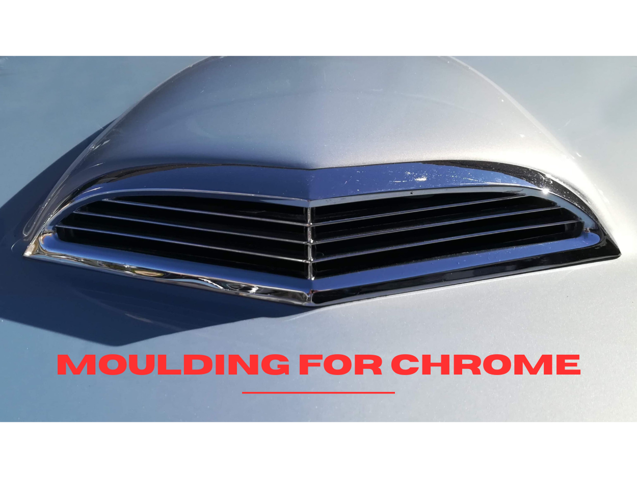
A chrome-plated plastic part is one of manufacturing’s more convincing illusions. It reflects like metal, carries the weight of quality like metal, and commands a price premium that plain plastic cannot. In an automotive interior, a premium bathroom fitting, or a high-end home appliance, it does its job beautifully, right until the moment it doesn’t.
Because here is what every Indian toolmaker who has worked on platable parts eventually learns about chrome parts: chrome does not hide defects; it is very brutal and demands more than commitment, precision, and capability. It announces them. A weld line that might pass unnoticed on a painted surface becomes a permanent dull streak under chrome. An ejector pin witness mark that looked minor in the tool becomes a rejection at the plating shop. A cooling non-uniformity that caused barely visible sink on a standard cosmetic part causes peeling and blistering after the electroplating process.
The toolrooms that do well in this segment, and increasingly, Indian OEMs in automotive, sanitaryware, consumer electronics, and appliances are asking their vendors for platable parts are the ones that understand one thing early: the plating process begins at the mould design stage, not at the plating vendor’s facility. Every decision made in the tool either supports a good plating result or quietly works against it.
Material Is the Starting Point
The first mistake many tool rooms make is treating plating-grade ABS (Acrylonitrile Butadiene Styrene ) tooling the same as standard cosmetic ABS work. The materials look similar, process at similar temperatures, and produce parts that come off the press looking largely identical. The difference only becomes visible after the etch.
During electroplating on plastic, the part is immersed in a chromic acid solution that selectively attacks and removes the butadiene rubber phase from the surface of the ABS, leaving behind a microporous structure. It is this micro-roughness that the subsequent metal layers, electroless copper, acid copper, semi-bright nickel, bright nickel, and finally chrome, grip onto mechanically. Without a consistent etch, there is no consistent adhesion. And without the right material, the etch is never consistent.
Standard ABS, high-flow ABS, flame-retardant grades, and material with high regrind content all respond differently to the etching step. The result is patchy adhesion, blistering, or peeling, problems that get blamed on the plating vendor but trace directly back to material specification.
What the toolmaker controls, however, is how the material is processed. Platable ABS injection moulding requires mould temperatures between 60°C and 80°C, higher than what most standard cosmetic tools run, to develop adequate surface crystallinity and reduce moulded-in stress. A cooling circuit designed purely to minimise cycle time will run the tool too cold, produce parts with inconsistent surface structure, and create a chrome result that is dull and patchy in areas regardless of what happens downstream.
Residual stress is the deeper problem. Wherever the polymer carries stress, at sharp internal corners, near the gate, or at wall-Thickness transitions, the material structure differs from the surrounding areas. The etch attacks these zones differently. The plating adhesion differs. And the result is visible: a line, a patch, a blister, exactly where the stress concentration was. Residual stress in a plated part is a tooling problem. It cannot be corrected at the plating stage.
Steel Selection, Surface Finish, and the Direction
For chrome-plated plastic mould design, steel selection matters more than it does for general cosmetic tooling for two reasons. First, the mould surface finish must reach the SPI A1 or A2 standard, and not all steels are capable of sustaining that level of polish through a production run. Second, the cooling water running through a standard P20 tool will eventually cause surface rust in the cavity. Rust marks on the mould surface are reproduced faithfully on the moulded part and announced permanently by the chrome layer.
NAK80 steel for mould making has become the practical default for platable moulds in India, pre-hardened to around 40 HRC, machined well, and polished to a reliable mirror finish. For sanitaryware and bathroom fittings where the tool operates in a humid environment with frequent water exposure, S136 or STAVAX stainless tool steel is the better choice despite the higher cost and longer machining time. The corrosion resistance justifies itself quickly when the alternative is rust marks on a chrome surface.
The polishing itself is where tools frequently fall short, not in the grade achieved, but in the direction. The cavity surface must be polished in the direction of part ejection, not against it. Polishing against the draw creates micro-undercuts that resist part release, drag across the surface during ejection, and introduce surface stress at the very last step of the process. This detail is understood instinctively by experienced polishers but is the kind of thing that produces a first plating rejection in a tool room new to the segment.
Simulation Is Not Optional for Chrome Plated Parts
For standard injection-moulded parts, a weld line is managed, pushed to a low-stress area, accepted as a cosmetic trade-off in some locations, and minimised where it matters. For chrome-plated parts, the position is simpler and stricter: no weld lines on any plated surface. A weld line under chrome shows as a dull streak or a crack line caused by two flow fronts meeting at reduced temperature and fusing incompletely, creating a surface structure that the etch attacks differently. After plating, it is there permanently.
This makes Moldflow simulation for platable parts non-negotiable, not a value-add. Gate location must be validated through filling analysis with the specific objective of confirming that weld lines are pushed entirely off plated surfaces behind a rib, onto a non-visible face, at a parting line. If the geometry makes this impossible with a single gate, a second gate is the right engineering answer, not a compromise.
Gate type matters equally. Valve gates on hot runner systems are the preferred choice for volume production of platable parts, clean gate witness, no cold slug, and the process control to manage fill velocity and switchover precisely. An undersized gate driving material at high velocity generates shear heat at the gate land, degrades the material surface locally, and produces a textured zone near the gate that chrome will permanently record. Gates for platable parts must be sized for controlled velocity, not restricted, to manage fill.
Submarine gates work where the break point is entirely off the plated surface. Pin gates on cosmetic surfaces should be avoided; the gate witness area is always a stress concentration that plates differently and fails adhesion testing under thermal cycling.
Ejection, Cooling, and the Failure Modes That Point Back to the Tool
Ejector pin witness marks on plated surfaces are not a finishing problem they are an ejection design problem. The pin contact creates a stress concentration that shows as a circular witness in the chrome. On a flat, reflective surface, it cannot be missed. The approach for platable moulds is to move all ejection off cosmetic surfaces entirely onto ribs, internal walls, and non-visible faces. Where geometry forces ejection onto a visible area, stripper plates distribute the force over a larger area and eliminate the concentrated contact stress of a pin.
Ejection balance matters as well. Uneven ejection, where one side of the part moves before the other, causes the part to flex during release, locking in stress that the plating adhesion test will find. Uniform, simultaneous ejection across the part is not a detail, it is a dimensional stability and plating adhesion requirement.
Cooling circuit design for platable moulds targets one outcome above all others: uniformity. Not average temperature uniformity across the entire cavity surface. A hot spot in the tool creates a zone of differential shrinkage, higher residual stress, and different surface crystallinity. Chrome on that zone will look different and adhere differently. Baffles and bubblers must reach deep cores and ribs. Separate circuits for zones with significantly different thermal loads allow independent control. For high-volume platable tools, conformal cooling inserts increasingly available through metal additive processes in India produce the kind of surface temperature uniformity that conventional drilling cannot match.
One practical detail that is frequently missed: chrome plating builds up on edges and inside holes, typically 15 to 30 microns per surface. A hole designed to a precise diameter will be smaller after plating. For parts with press-fit pins, thread inserts, or mating faces, this must be designed into the mould from the start.
Usual Causes of Rejection
When parts come back from the plating shop, the failure mode is information. Peeling or blistering in a localised area points to residual stress; check sharp corners, the gate vicinity, and ejection contact points. Dull patches or streaks indicate weld lines or surface contamination; review the gate location through simulation and check material handling at the press. Pitting across the surface suggests steel porosity or rust marks from the cooling circuit steel grade and water quality are the starting points. Cracks in the chrome after thermal cycling point to warpage from uneven cooling or insufficient wall thickness. The cooling circuit and wall section design need review.
Every one of these failures has a tooling root cause. The plating vendor can adjust chemistry and process parameters, but they cannot fix a weld line that runs across a plated face, an ejector pin stress concentration, or a cooling hot spot that produces differential shrinkage. Those are tool room problems that must be solved in the design office.
Discipline That Actually Produces First-Time-Right Results
Platable mould work is not dramatically more complex than high-quality cosmetic mould work. The principles that control the surface, control the stress, and control the temperature are the same. What changes is the tolerance for variation. Where a standard cosmetic part absorbs a minor surface imperfection or slight cooling non-uniformity without visible consequence, a plated part surfaces both, in chrome, permanently.
The Indian toolrooms winning platable work consistently are not necessarily the largest. They are the ones that confirm material specification before the tool design begins, run Moldflow before steel is ordered, track mould temperature as a controlled process parameter, and investigate a plating rejection as a tooling problem rather than a vendor dispute.
That discipline applied at the design stage, not recovered at the trial stage, is what first-time-right tooling for chrome-plated parts actually looks like. And in a segment where customer expectations continue to rise and the cost of a rejected plated part is felt across the entire supply chain, getting it right the first time is not just good practice. It is the only position that is commercially sustainable.