
Ask a mould designer where the gate should go, and the instinctive answer is often “wherever it’s easiest to machine and least visible. “That answer isn’t wrong, exactly; it’s just incomplete. Gate location is one of the few decisions in mould design that simultaneously controls fill pattern, weld line position, packing efficiency, shrinkage behaviour, warpage, and cosmetic outcome. Move it a few millimetres, and you can shift a weld line off a structural boss, change which wall packs out fully, or turn a cosmetic reject into a good part.
This is why gate location deserves the same design-stage attention as draft, parting line, or ejector layout, not a decision made after the cavity is already modelled.
What the Gate Actually Controls
The gate isn’t just an entry point for molten plastic. It sets the starting condition for everything that happens inside the cavity during fill and pack:
-
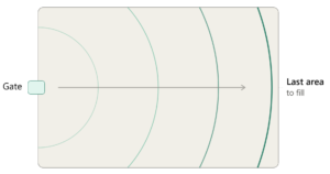
Fill pattern – where the melt front starts and how it advances determines flow length, flow balance, and where the mould fills last.
-
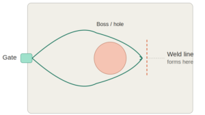
Weld and meld lines – wherever two flow fronts meet, you get a line of reduced strength and often reduced cosmetic quality. The gate position decides where that meeting happens.
-
Packing pressure transmission – the gate is the last point of pressure transfer before it freezes off. Areas far from the gate, or areas that pack through a restrictive section, are more prone to sink and voids.
-
Shear and orientation – melt shear near the gate affects local molecular/fibre orientation, which shows up later as differential shrinkage.
-
Vestige and cosmetic mark – the gate leaves a mark, however small. Where that mark lands is a cosmetic and sometimes functional decision.
Get the gate location right, and you’re managing all five of these simultaneously. Get it wrong, and you’re usually fighting one of them in production, often the hard way, with process tweaks that only partially compensate for a geometric decision made months earlier.
The Factors That Actually Drive Gate Placement
1. Wall thickness transitions.
Melt naturally wants to flow from thick sections to thin ones. Gating into a thin section and expecting it to fill a thick boss downstream is asking for trouble; the reverse, gating into the thickest section and letting flow move toward thinner walls, generally packs and fills more predictably.
2. Flow length and flow-length-to-wall-thickness ratio.
Every material has a practical flow length limit for a given wall thickness and processing window. Gate location determines the actual flow distance the melt has to travel to reach the farthest point of the cavity. A gate placed off-centre on a long, thin part can push one end well past the material’s comfortable flow ratio, leading to short shots or excessive packing pressure.
3. Weld line tolerance.
Every multi-gate or obstructed-flow part will generate weld lines somewhere. The design question isn’t whether to avoid them entirely; it’s whether you can push them into a location that isn’t structural or cosmetic. Around bosses, ribs, and holes, flow fronts split and rejoin; gate position determines exactly where that rejoining happens.
4. Cosmetic surface constraints.
On a Class-A or high-gloss surface, gate vestige is not acceptable. This pushes gate location toward non-visible faces, undercuts, or into features like ribs and bosses where a sub-gate or tunnel gate can hide the mark entirely, tying gate strategy directly back to cosmetic surface planning.
5. Structural and dimensional requirements.
Gating directly into or near a critical dimensional feature can introduce local stress, orientation effects, or a witness mark exactly where tight tolerance is needed. Structural ribs and bosses are often deliberately kept away from the gate for this reason, unless the gate is specifically routed through them via a sub-gate.
6. Venting and air entrapment.
The gate position sets the fill direction, which in turn determines where air gets pushed to. If the gate placement drives the melt front toward a location with no vent path, a deep pocket, a boss cluster, or a far corner, you get burn marks or short fills that no amount of process tuning fully resolves.
Gate Type Changes the Location Conversation
The type of gate isn’t a separate decision from location; the two are linked.
-
Edge gates sit on the parting line and are straightforward to machine, but they restrict placement to the part’s perimeter.
-
Sub-gates / tunnel gates allow gating from underneath the part, away from the parting line, which opens up cosmetic-surface-friendly locations at the cost of added tool complexity.
-
Pin gates (typically in three-plate or hot runner tools) allow gating almost anywhere on the part, including directly into the centre of a surface, useful for symmetrical fill on round or box-like parts, but the vestige has to be planned for.
-
Fan and tab gates are used to control flow velocity and reduce shear at the entry point, often where a standard edge gate would cause jetting.
-
Diaphragm gates are specific to circular parts needing a weld-line-free fill, gating through the centre bore.
Choosing “where” without first settling “what type” often leads to a location that’s technically ideal for flow but physically impossible to tool.
Balancing Gates in Multi-Cavity and Family Tools
In single-cavity tools, gate location is a flow and cosmetic problem. In multi-cavity or family tools, it becomes a balancing problem as well. Every cavity needs to fill at approximately the same time and pressure, or some cavities will be overpacked while others are underpacked.
This situation is where naturally balanced runner layouts matter, geometrically equal flow lengths from the sprue to each gate versus artificially balanced layouts, where gate size or land length is adjusted to compensate for unequal runner lengths. Naturally balanced layouts are more forgiving in production; artificially balanced ones require tighter process control and are more sensitive to material lot variation.
Warpage: The Consequence That Shows Up Later
Gate location has a delayed effect that often gets missed until first-shot inspection: warpage. Flow direction influences molecular or fibre orientation, and shrinkage is rarely uniform along versus across that orientation, particularly with glass-filled or semi-crystalline materials. A gate that creates a flow front travelling primarily in one direction across a flat panel can produce differential shrinkage that shows up as bow or twist, even when wall thickness is uniform and cooling looks balanced on paper.
This is a genuine trade-off point worth stating plainly: the gate location that gives the best cosmetic and weld-line outcome is not always the one that gives the flattest part. Tool designers sometimes have to pick which failure mode they’d rather manage in production.
Common Mistakes Worth Naming
-
Gating based purely on ease of machining or runner routing, without a flow simulation to check fill balance.
-
Placing the gate on a cosmetic surface because it was the “obvious” central point, without checking sub-gate feasibility.
-
Ignoring flow-length-to-thickness ratio on long, thin parts until short shots appear in trial.
-
Gating near a critical dimensional feature and only discovering orientation-driven distortion after first-article inspection.
-
Treating gate size as purely a filling parameter, without considering its effect on vestige size and packing time.
What to Confirm Before the Gate Location Is Finalised
-
Wall thickness map and preferred flow direction (thick to thin)
-
Flow-length-to-wall-thickness ratio against material capability
-
Acceptable weld line zones (non-structural, non-cosmetic)
-
Cosmetic surface boundaries and vestige tolerance
-
Gate type feasibility given tool budget and cycle time targets
-
Venting path implied by the resulting fill pattern
-
Cavity balance requirement, if multi-cavity
-
Anticipated shrinkage/orientation risk on critical flat or structural sections
The Real Principle
Gate location isn’t a single decision; it’s the point where material flow behaviour, part geometry, cosmetic requirements, and tooling complexity all intersect. Treating it as a late-stage placement exercise, decided after the cavity is modelled, is how avoidable weld lines, warpage, and cosmetic rejects end up discovered in trial instead of in design review.
The gate is the first thing the melt sees and the last thing packing pressure travels through. Everything else in the cavity is downstream of that one decision.