
Moving Beyond Rules of Thumb to Engineering-Led Gate Selection!
Walk into most toolrooms in India and ask a senior toolmaker how he chose the gate for a particular mould. The answer, more often than not, will reference experience. “We’ve always done it this way for this kind of part.” That experience is valuable, but it is no longer enough.
Today’s customers, automotive OEMs, electronics brands, and medical device makers are demanding shorter development cycles, first-time-right tooling, and export-grade consistency. The old way of selecting a gate, adjusting it during trials, reworking the tool, and hoping for the best is too expensive and too slow. Gate selection has become an engineering decision. And the best toolrooms in India are already treating it that way.
Start with the Part, Not the Gate
The single biggest shift in thinking is this: gate selection begins with understanding what the component must achieve, not with choosing a gate type from a chart.
Before anything else, ask:
- What are the structural requirements? Does it carry load, absorb impact, hold a thread?
- What are the cosmetic requirements? Is any surface visible to the end user?
- What are the dimensional tolerances? Is this part assembled with tight clearances?
- What is the production volume, and is degating manual, automatic, or robotic?
- What is the cycle time target?
These questions seem obvious, but they are frequently skipped. A toolmaker who answers all of them before touching the mould design will arrive at a better gate decision than one who relies on habit alone.
Five Engineering Questions That Drive the Decision
Rather than picking a gate and working backwards, experienced toolmakers work through a structured set of questions.
- How will the polymer actually flow?
Every material behaves differently under pressure and shear. A gate that works beautifully for unfilled PP can cause degradation and burn marks in a glass-filled nylon. Flow length, pressure drop across the gate, shear rate at the gate land, and material sensitivity all determine whether the gate will fill the cavity cleanly or create problems from the first shot. This is where simulation not intuition gives you the answer.
- Where does packing pressure need to reach?
Sink marks appear where packing is inadequate. Thick sections, ribs, and bosses are the usual suspects. The gate must be positioned where it can maintain effective packing pressure in these areas through the pack and hold phase. A gate that fills the cavity but cannot pack the critical sections will produce parts that look acceptable on the surface and fail dimensional checks on the bench.
- Where can the gate leave a mark, and where absolutely cannot it?
This is a customer conversation, not a toolmaker’s decision. Visible surfaces, Class-A automotive parts, and decorative consumer products have zero tolerance for gate witness marks. Functional surfaces that mate with other components may have equally strict requirements. Defining the cosmetic and functional no-go zones before gate placement saves rework that nobody wants to pay for.
- How will the part be delegated, and who will do it?
A submarine gate for an automated line is a completely different design from a tab gate for a manually operated press. If a robot is picking the part, the gate breakoff must be predictable, clean, and in a location the end-of-arm tooling can access. If the line runs 24 hours, manual degating is a bottleneck. Gate type and degating method must be designed together, not decided separately.
- Can this gate actually be manufactured and maintained?
This is the question most design office articles never ask. A gate design that looks elegant in CAD may be a nightmare to EDM, difficult to polish, impossible to repair without pulling the insert, and prone to wear after 100,000 shots. Experienced toolroom engineers think about insert accessibility, EDM electrode paths, wire-cut requirements, replaceable gate inserts for high-wear applications, and what happens when the gate needs rework six months into production.
How Specifically Simulation Helps
Moldflow and similar CAE tools have moved from luxury to necessity in serious toolrooms. But the value isn’t just in pressing “solve” and accepting the output, it’s in what experienced engineers read from the results.
Filling analysis shows whether the cavity fills progressively without short shots, hesitation, or race-tracking. Pressure analysis confirms whether the required injection pressure and clamp force are within the machine’s capability, an important check before the tool is cut. Weld line prediction identifies where flow fronts meet, so gate location can be adjusted to push weld lines away from structural or cosmetic areas. Warpage analysis shows how gate position interacts with cooling to influence final part geometry.
For glass-filled materials, increasingly common in Indian automotive and industrial tooling, fibre orientation analysis is essential. The gate determines how fibres align, which directly affects the part’s mechanical performance. This is not something you can correct at the moulding machine.
One area that is frequently under-appreciated: the gate cannot be designed independently from the cooling circuit. A gate positioned over a poorly cooled area will extend cycle time, increase residual stress, and contribute to warpage. Cooling and gating must be engineered together.
Matching Gate Type to Engineering Objective
Gate types are tools, not traditions. The selection should be driven by what the part demands.
| Engineering Objective | Suitable Gate Types |
| Thin-wall filling | Fan, Film |
| Cosmetic surfaces | Tunnel, Valve Gate |
| High-volume automated production | Valve Gate, Pin Gate |
| Large structural parts | Direct (Sprue), Fan |
| Automatic degating without hot runner | Submarine (Tunnel) |
| Balanced multi-cavity filling | Multiple Pin Gates, Valve Gates |
| Fibre-filled materials | Edge, Fan (with simulation) |
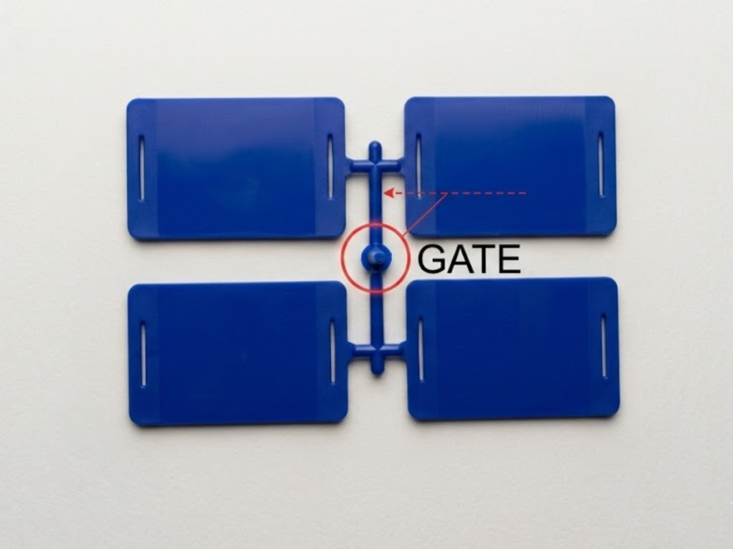
Each gate type has practical limitations. Submarine gates perform well for automatic degating, however they are susceptible to gate land wear in abrasive materials. Fan gates provide great flow dispersion, but they leave a larger witness mark and require trimming. Valve gates provide the cleanest cosmetic result and the best process control, but they need maintenance discipline and increase tooling costs.
Hot runner systems, formerly considered luxury, are now the norm for automotive and electronics manufacturing in India. Sequential valve gating, which involves opening and closing valve pins in a specific order, is increasingly utilised to control weld line location and balance filling in large or asymmetric sections. The investment is real. The return is measured in cycle time, material savings, and process consistency.
Mistakes That Send Tools Back for Rework
The most expensive gate decisions are the ones made too early or too late. Common mistakes that experienced toolmakers have learned to avoid:
- Fixing the gate location before wall thickness is finalised
- Ignoring shear sensitivity in engineering polymers like POM or PC
- Undersizing the gate to “save steel” causing excessive injection pressure and material degradation
- Overlooking venting near the gate, which leads to burn marks and incomplete filling
- Running simulation after the steel has been cut, when the results can inform only minor adjustments
- Treating gate selection as separate from cooling design
The Shift Happening in Indian Toolrooms
The better toolrooms in India are already operating differently. DFM reviews happen before design release. Simulation is run before steel is ordered. Gate location is validated digitally, not discovered during trials. Hot runner suppliers are brought in early. Trial counts are tracked as a performance metric.
This shift is being driven partly by export requirements, customers in Europe and North America expect process data, not just sample parts, and partly by economics. Every trial that can be eliminated saves time, material, machine hours, and the kind of stress that keeps toolroom managers up at night. The talent to do this work exists in India. What is changing is the expectation that it will be applied systematically, not selectively.
Before freezing any gate design, work through these ten steps:
- Define part function: structural, cosmetic, dimensional priorities
- Study the material: flow behaviour, shear sensitivity, fibre content
- Evaluate wall thickness and flow path length
- Identify cosmetic and functional no-go zones
- Determine production volume and degating method
- Select runner concept: cold runner, hot runner, or valve gate
- Validate gate location using filling, pressure, and weld line simulation
- Assess manufacturability: EDM access, insert design, repairability
- Design cooling around the gate, not independently of it
- Freeze the design only after digital validation confirms it
Gate selection is where a mould’s success or failure is often decided, long before the first shot is ever taken. The toolrooms that understand this are the ones building reputations that last.