

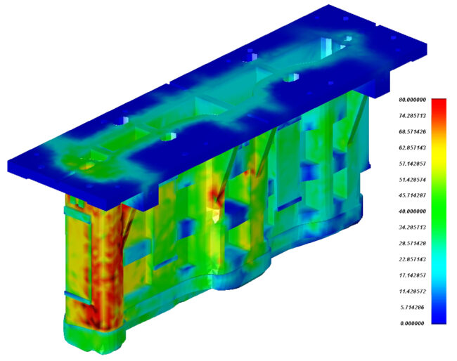
Sheet metal design is a complex field that requires consideration of material properties, manufacturing processes, and product functionality. Metals used in sheet form are chosen for their malleability, strength, and durability. However, designing with these materials demands a deep understanding of factors like bend allowance, which accounts for the material’s stretch and compression during bending, and the impact of corner treatments and hole placements on the final product. This is where Finite Element Analysis (FEA) steps in, revolutionizing the sheet metal design landscape.
By – Shashank Patake
How Does FEA Work?
FEA is a powerful computer-aided engineering (CAE) practice that simulates the behaviour of complex structures under various loading conditions. It works by breaking down the entire structure into a mesh of smaller, simpler elements – finite elements. Mathematical equations are then applied to each element to analyze its behaviour and how it interacts with neighbouring elements. By combining the analysis of all these elements, FEA software can predict the overall response of the entire structure under the loads.
Imagine a sheet metal bracket. Using FEA, the bracket can be virtually divided into a mesh of tiny squares. The software then analyzes each square under various load scenarios, such as a force applied at a specific point. By understanding how each square reacts, the software can predict how the entire bracket will deform or potentially fail. This virtual testing capability empowers designers to optimize sheet metal designs before investing time and resources into physical prototypes.
The Advantages of FEA in Sheet Metal Design
FEA offers a plethora of benefits that streamline and optimize the sheet metal design process. Here are some key advantages:
- Enhanced Design Efficiency: FEA allows designers to virtually test and analyze numerous design iterations before committing to physical prototypes. This significantly reduces development time and costs associated with building and testing multiple prototypes. Imagine designing a car hood. With FEA, you can virtually test different thicknesses and reinforcement ribs to ensure optimal strength and weight reduction before building a single physical prototype.
- Optimized Material Usage: Sheet metal is often a cost-sensitive material. FEA helps identify areas of over-engineering where material thickness can be reduced without compromising the design’s integrity. This not only saves on material costs but also reduces the overall weight of the final product, potentially leading to improved fuel efficiency in vehicles or better handling characteristics in other applications. Some of the FEA software also help in predicting the blank outline and nesting. The result yields higher material utilization rate and more practical nesting layout of blanks.
- Predicting Formability Issues: Sheet metal forming processes like bending, deep draw, flanging etc. can introduce challenges like tearing, wrinkling, or springback (the tendency of the metal to return to its original shape after forming). FEA simulations can predict these potential issues early in the design stages. This allows designers to adjust the design or tooling to ensure a smooth forming process and a defect-free final product.
- Reduced Reliance on Physical Prototyping: The ability to virtually test designs with FEA reduces the need for numerous physical prototypes. This not only saves time and resources but also minimizes material waste associated with discarded prototypes.
Applications of FEA in Sheet Metal Design
The versatility of FEA extends to various aspects of sheet metal design:
- Sheet Metal Forming: Analyzing the behaviour of sheet metal under different forming processes like bending, drawing, flanging, trimming etc. allows for the optimization of tooling design and process parameters to achieve the desired shape without defects.
- Strength and Stiffness Analysis: Predicting the stress and strain distribution on the sheet metal component under applied loads helps ensure the design can withstand real-world working conditions without excessive deformation or failure.
- Fatigue Life Prediction: Components subjected to repeated loading cycles, such as engine brackets, appliance components or even the tooling, are susceptible to fatigue failure. FEA simulations can predict the fatigue life of the component by simulating the effect of these repeated loads, allowing for design modifications to improve its longevity.
- Thermal Analysis: Analyzing the thermal behaviour of the sheet metal component becomes crucial in applications involving heat transfer or potential warping due to temperature variations. FEA can predict how the component will respond to thermal loads, enabling designers to incorporate heat sinks or adjust material selection for better thermal management.
Future of FEA in Sheet Metal Design
The future of FEA in sheet metal design promises even greater efficiency and accuracy. Advancements in material modelling will enable more precise simulations that account for the complexities of sheet metal behaviour. Additionally, improved integration between FEA software, CAD systems, and manufacturing processes will create a more streamlined workflow, from design concept to production. These advancements will empower sheet metal designers and manufacturers to push the boundaries of innovation and create lighter, stronger, and more efficient sheet metal components.
To unlock the full potential of FEA in your sheet metal design workflow, consider powerful solutions like Dynaform 7.1. This comprehensive software offers user-friendly tools for simulating sheet metal forming processes, optimized die face design, nesting, and more. Request a free demo today to experience how Dynaform 7.1 can streamline your sheet metal and die design process to ensure first-time-right part production.
About The Author:

Shashank Patake is the Director of Sales and Partner Engagement at Engineering Technology Associates, Inc. He excels in business development, GTM strategy, account and territory development. Shashank’s expertise spans CAD/ECAD, CAE and EDA industries, and he is known for effective management and continuous improvement.